PRINCIPLES OF SPEY MECHANICS
The foundational mechanical system that governs Spey casting in all environmentsBy Mark Severino

OverviewSpey Mechanics defines Spey casting as a mechanical discipline, not a river-restricted technique. These principles apply in all environments:
• rivers
• surf
• lakes
• estuaries
• tidal rivers
• inlets
• reservoirsSpey can be fished or practiced in any body of water.The environment only changes how tension is created, not the mechanics themselves.THE PRINCIPLES
0. Continuous TensionThe rod only loads when the line is alive. Continuous tension governs every mechanical action in Spey casting.
Tension must remain unbroken through:
• anchor
• D loop
• apex
• stroke
• loop
• trajectory
Every collapse mode originates from a tension break.1. Forward, High Anchor Geometry
The anchor must land:
• forward
• high
• light
• aligned with the stroke plane
• tension-driven
Forward anchors stabilize tension direction, support rearward D-loop formation, and prevent apex collapse.Waterborne anchors are often the most stable anchor form when available, but they do not define Spey casting.2. Rearward, High D-Loop Mass
Rearward mass loads the rod and stabilizes apex height.
A correct D-Loop is:
• deep
• rearward
• high
• tension-driven
Minimal D-loops collapse under wind, chop, or slack. Rearward mass = rod load = loop compression = distance.3. Rearward, High Apex Plane
The apex is the geometric launch platform.
Apex must be:
• high
• rearward
• level
• continuous with the stroke plane
• tension neutralApex height determines:
• trajectory height
• loop stability
• drag profile
• distance ceiling
Apex collapse is among the most common failure modes across environments.4. Vertical Stroke Plane
The rod tip can travel on the chest–shoulder seam plane.The vertical stroke plane is defined anatomically by the chest–shoulder seam, the natural forward casting corridor of the human body. This seam preserves apex height, tension direction, and straight-line tip path.The chest–shoulder seam aligns:
• the rod tip
• the apex
• the rearward mass
• the forward stroke
• the trajectoryThis alignment creates a continuous geometric corridor from anchor → D loop → apex → stroke → loop → trajectory.What Casting on the Seam prevents:
• apex drop
• forward apex drift
• diagonal tip path
• loop opening
• tension loss
• tip dip
• off-plane rotation
The shoulder seam maintains vertical apex continuity.Why the Seam Works in All Environments.The seam is biomechanical, not hydrodynamic. It stabilizes tension in:
• rivers
• lakes
• surf
• estuaries
• tidal flowThe rod does not know the environment — only the geometry of the tip path.5. Short Slide (1–2 inches)
Slide is the micromovement that:
• prevents early rotation
• preserves apex height
• maintains tension direction
• deepens the D-loopSlide must be short, controlled, and tension-driven.6. Short Translation (2-4 inches)
Translation is the linear phase of the forward stroke.
Correct translation:
• preserves tension
• builds stroke length
• maintains straight line tip path
• sets up late rotation
Translation is geometry, not power.7. Late Rotation
Rotation sets the launch vector.
Late rotation:
• compresses the loop
• preserves apex height
• stabilizes trajectory
• prevents tip dipEarly rotation destroys tension, collapses apex height, and opens the loop.Late rotation = loop compression = distance.8. Crisp Stop
The stop locks:
• trajectory angle
• loop height
• tip path
• forward vectorA crisp, high stop creates aerodynamic stability. Soft stops cause belly sag, drag increase, and early collapse.9. High, Level Trajectory
Trajectory is the aerodynamic continuation of the apex plane.
Correct trajectory is:
• high
• level
• compressed
• stableLow trajectories collapse under wind. Tilted trajectories destabilize loop geometry.High trajectory = long flight time = distance.10. Straight Line Rod Tip Path
The rod tip must travel in a straight line during the forward stroke.Straight line tip path ensures:
• tight loops
• stable turnover
• efficient energy transfer
• apex continuity
• maximum distanceThis is the geometric foundation of all Spey casting.Why Mechanics Do Not Change Across EnvironmentsSpey mechanics are defined by rod tip geometry, not water type.
The rod only understands:
• tension direction
• apex height
• stroke plane
• rotation timing
• trajectory angleIt does not know whether the caster is in a river, lake, surf, or estuary.
This is why the principles are universal.Tension Creation vs Tension Preservation
Different environments create tension differently:
• River: current creates tension automatically
• Lake: caster must create tension manually
• Surf: caster must create and protect tension
• Estuary/Tidal: tension fluctuates and must be stabilizedTension can be created by pulling/sweeping against a waterborne anchor or by sweeping against an aerialized reset; both methods produce the tension required for universal Spey mechanics.But once tension exists, preservation is identical:
• forward anchor
• rearward mass
• high apex
• vertical plane
• late rotation
• crisp stopMechanics are universal. Tension creation is environment-specific.The Geometry Chain
All Spey casts follow the same geometric sequence:
1. Anchor Geometry
2. D-Loop Geometry
3. Apex Geometry
4. Stroke Geometry
5. Loop Geometry
6. Trajectory GeometryEvery principle maps directly onto one link in this chain.
This chain is the backbone of the Unified Spey Doctrine.Failure Modes
Regardless of environment, all Spey casts can fail for the same reasons:
• apex too low
• apex too far forward
• D-loop too shallow
• anchor too heavy
• stroke plane too low
• rotation too early
• trajectory too lowSummary
Spey Mechanics define Spey casting in all environments:
• forward, high anchors
• rearward, high apex
• deep, tension-driven D-loops
• vertical stroke plane
• short slide
• short translation
• late rotation
• crisp stop
• high, level trajectory
• straight line rod tip pathThese principles form the mechanical core of Surf Spey, Lake Spey, Estuary Spey, Tidal Spey, and River Spey.Spey casting is not defined by rivers. Spey casting is defined by mechanics.
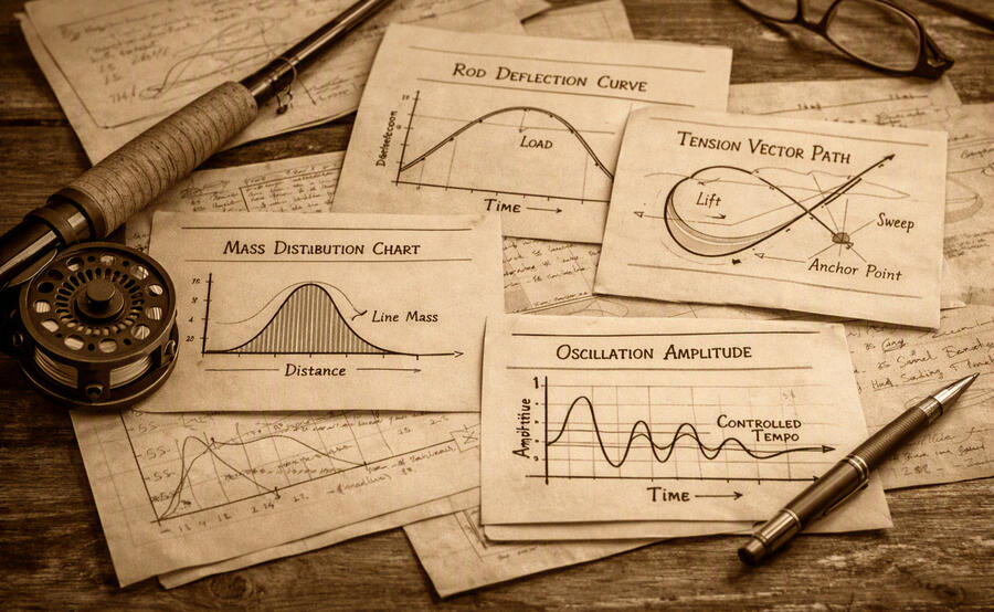
THE GEOMETRY CHAINThe sequential geometric system that governs every Spey cast in every environmentThe Geometry Chain is the second pillar of the Spey Doctrine. If Spey Mechanics defines what must happen, the Geometry Chain defines how it happens — the order, the geometric relationships, and the failure modes.Every Spey cast follows the same six-link geometric sequence:
Anchor Geometry, D-Loop Geometry, Apex Geometry, Stroke Geometry, Loop Geometry, Trajectory GeometryThis chain is universal because geometry is universal. The rod does not know the environment—only the geometry of the tip path.1. Anchor Geometry (Directional Origin)
The anchor is the cast’s directional origin. Its geometry determines tension direction, D-loop alignment, apex height, stroke plane alignment, loop stability, and trajectory angle.Correct anchor geometry is:
forward high light aligned with the stroke plane, tension-driven, placed inside the anchor laneThe anchor is not a spot. It is a lane — a directional corridor that defines the cast.2. D-Loop Geometry (Rearward Mass & Stored Tension)
The D-loop stores the tension created by the sweep and aligns rearward mass behind the apex.Correct D-loop geometry is:
Rearward, high, deep, tension-driven, aligned with the anchor lineThe sweep creates tension. The D-loop stores tension. The rod loads when rotation begins, and the stored tension resists forward tip movement.A D-loop that is too shallow, too forward, too low, or too slack collapses the apex and breaks the geometry chain.Rearward mass plus stored tension loads the rod only during rotation.3. Apex Geometry (Launch Platform)
The apex is the cast’s geometric launch platform.Correct apex geometry is:
high rearward level tension neutral continuous with the stroke planeApex height determines loop stability, drag profile, flight time, and distance ceiling. Apex collapse is the primary failure mode in all environments.4. Stroke Geometry (Rod Tip Path)
The stroke is the geometric corridor that delivers the cast.Correct stroke geometry is:
Vertical, straight, tension-driven, aligned with the apex, aligned with the anchor line, aligned with the D-loopThe chest–shoulder seam is a highly stable biomechanical stroke plane. It is biomechanical, not hydrodynamic.5. Loop Geometry (Energy Compression)
The loop is the aerodynamic continuation of the stroke.Correct loop geometry is:
High, compressed, stable, aligned with the apex planeLoop geometry is determined by a straight-line rod-tip path, late rotation, a crisp stop, and apex height.Wide, tilted, or collapsing loops originate from geometric failure.6. Trajectory Geometry (Flight Path)
Trajectory is the aerodynamic continuation of the apex.Correct trajectory geometry is:
high-level, compressed, stableTrajectory collapse is caused by low apex, early rotation, soft stop, diagonal tension, or off-plane stroke.Trajectory is the final link in the chain — but it is determined by every link before it.Summary
The Universal Geometry Chain defines the sequential structure of every Spey cast:
Anchor establishes direction.
D-loop stores tension and rearward mass.
Apex forms the launch platform. Stroke delivers the cast.
Loop compresses energy. Trajectory carries the flight.Geometry is universal. Mechanics are universal. Only tension creation changes with the environment.